length, distance, sqrt

coonextions.gif

I was really amazed the first time I saw a similar visualization on the Processing homepage…err, like 10 years ago. It’s such a simple concept, but very pretty. Anyway, I finally sat down and gave it a go in glsl. While working with it I played around with the distance calculations and figured I should write a tiny bit about that.

When you need to calculate the distance between two points, you have a few options. You can write a function yourself, or use one of the built-in functions in glsl: distance(), length(), or sqrt(). distance() takes in two vectors. length() accepts 1 vector and sqrt() takes in a float (typically). But sometimes you don’t need the exact distance. Sometimes you’re just trying to find out if the length of a vector is longer than some defined value. In these situations you can use the squared distance instead.

For the squared distance you just need to get the difference between vector A and B then assign to say, C. The squared distance would then be: c.x*c.x+c.y*c.y. Or even: dot(c,c); So basically it’s everything length does without the call to sqrt–which is the computationally expensive part.

The values returned from these two methods (sqrt distance and squared distance) are of course fundamentally different, so you’ll need to adjust the value you are comparing against if you switch between the two.

Visualizing SDFs: Flies & Force Fields

cylinder

I’ve been spending quite a bit of time learning shaders and with that, learning SDFs (Signed Distance Functions). SDFs are very useful for rendering geometric shapes. There’s certainly a beauty to them–composed basically of just a bunch of math. Often void conditionals, they are efficient, but not so readable.

When first learning to read SDFs, it can be daunting. Just take a look at the definition for a cylinder:

float sdCylinder(vec3 p, vec2 sz ){
  vec2 d = abs(vec2(length(p.xz),p.y)) - sz;
  float _out = length(max(vec2(d.x,d.y), 0.));
  float _in = min(max(d.x,d.y), 0.);
  return _in + _out;
}

Errr, what? A month ago, I would have given up after the second line. Certain visualization tools are necessary to help break apart the logic, which is what this blog is all about.

Anyway, this week I was in process of understanding a cylinder SDF and I had a neat insight. Understanding the logic is much easier if visualized with flies and force fields.

Game Rules

In this world, our object is enveloped in force fields. Each field has a fly trapped inside. Poor dudes. Flies cannot pass between the fields. There’s the “tube” force field that defines the radius of the cylinder and force fields along the XZ-planes controlling the height.

There’s also a fly trapped inside the object itself and another stuck directly on the cylinder. Other than not being able to pass between fields, the flies (our sample points) are free to travel anywhere inside the field. And each case, there is a straight-line distance from the fly/point to the object. The force fields represent the different cases of our logic. Hmmm, a diagram might help:

labels

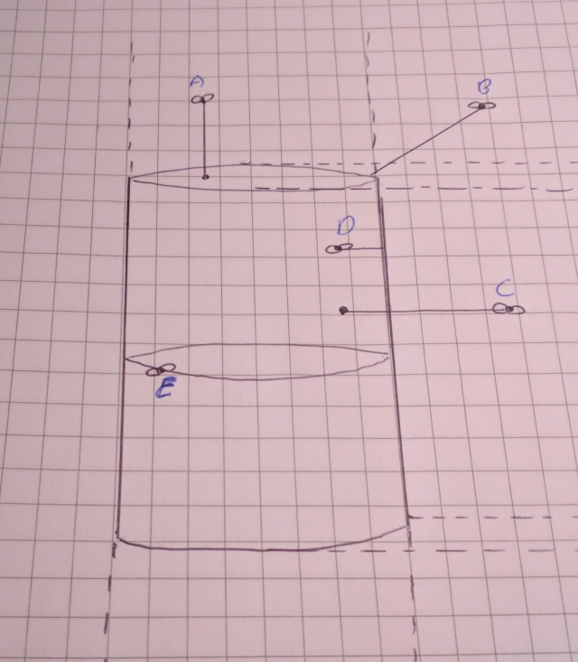
If you spend a bit of time visualizing each case separately, seeing the flies buzzing in their respective fields, it becomes more clear how the different parts of the logic work.

dist

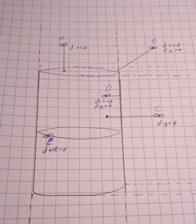
Fly A: (y – height) => (Cylinder Top)
Fly B: length of vec2(p.xz – radius, p.y – height) => (Cylinder Rim)
Fly C: length of (p.xz – radius) => (Cylinder Body)
Fly D: greater of length of (p.xz – radius) OR (y-height) => (Inside Cylinder)
Fly E: distance = zero, strictly lives on cylinder

Okay, let’s dive in.

float sdCylinder(vec3 p, vec2 sz ){

Easy stuff here. Return a float since which is our distance from the sample point to the surface of the object. The two parameters are a vec3 p and a vec2 sz. The sz variable contains the radius and height of the cylinder as its x and y components respectively.

vec2 d = abs(vec2(length(p.xz),p.y)) - sz;

The vec2 defined contains p.xz distance from the origin and p.y. We use abs since a cylinder is symmetrical and only the “top right front” part needs to be evaluated. Everything else is just a “mirror” case. Subtracting sz yields the differences for both the “top” and “body” distances. Store that in d.

float _out = length(max(vec2(d.x, d.y), 0.));

Using max with zero isolates which case we’re working with. If the point/fly is at the top of the cylinder, then d.x < 0. If it is in the ‘body’ force field, it’s d.y 0 and d.y > 0, the we’re dealing with fly B. The neat part is that either we’ll have one component set to zero in which case length is just using 1-dimensions, or we’ll have 2 components, which case length still works.

float _in = min(max(d.x,d.y), 0.);

Lastly, if the fly is trapped inside, then which surface is it closer to? Top or body? d.y or d.x? Use max to find that out. If one of the values are positive here, min is used to set it to zero. Think of min here as a replacement to a conditional.

Again, here is the final definition:

float sdCylinder(vec3 p, vec2 sz ){
  vec2 d = abs(vec2(length(p.xz),p.y)) - sz;
  float _out = length(max(vec2(d.x,d.y), 0.));
  float _in = min(max(d.x,d.y), 0.);
  return _in + _out;
}

This visualization tool has helped me to deconstruct the SDF logic. I hope it has been of use to you too! I suggest memorizing the five cases where the fly/point can exist. Then you can derive the code from scratch if necessary–it’s a good way of testing your understanding. It’s also really fun once you grasp it!

Understanding Vector Reflection Visually

I started experimenting with normal maps when I came to the subject of specular reflection. I quickly realized I didn’t understand how the vector reflection part of the algorithm worked. It prompted me to investigate exactly how all this magic was happening. Research online didn’t prove very helpful. Forums are littered with individuals throwing around the vector reflection formula with no explanation whatsoever. This forced me to step through the formula piecemeal until I could make sense of it. This blog post attempts to guide readers through how one vector can be reflected onto another via logic and geometry.

Vector reflection is used in many graphics and gaming applications. As I mentioned, it is an important part of normal mapping since it is used to calculate specular highlights. There are other applications other than lighting, but let’s use the lighting problem for illustration.

Let’s start with two vectors. We would know the normal of the plane we are reflecting off of along with a vector pointing to the light source. Both of these vectors are normalized.


L is a normalized vector pointing to our light source. N is our normal vector.

We are going to work in 2D, but the principle works in 3D as well. What we are trying to do is figure out: if a light in the direction L hits a surface with normal N, what would be the reflected vector? Keep in mind, all the vectors here are normalized.

I drew R here geometrically, but don’t assume we can simply negate the x component of L to get R. If the normal vector was not pointing directly up, it would not be that easy. Also, this diagram assumes we have a mirror-like reflecting surface. That is, the angle between N and L is equal to the angle between N and R. I drew R as a unit vector since we only really care about its direction.

So, right now, we have no idea how to get R.
R = ?

However, we can use some logic to figure it out. There are two vectors we can play with. If you look at N, you can see that if we scale it, we can create a meaningful vector, call it sN. Then we can add another vector from sN to R.

What we are doing here is exploiting the parallelogram law of vectors. Our parallelogram runs from the origin to L to sN to R back to the origin. What is interesting is that this new vector from sN to R has the opposite direction of L. It is -L!

Now our formula says that if we scale N by some amount s and subtract L, we get R.
R = sN - L

Okay, now we need to figure out how much to scale N. To do this, we need to introduce yet another vector from the origin to the center of the parallelogram.

Let’s call this C. If we multiply C by 2, we can get sN (since C is half of the diagonal of the parallelogram).
2C = sN

Replacing sN in our formula with 2C:
R = 2C - L

Figuring out C isn’t difficult, since we can use vector projection. If you are unsure about how vector projection works, watch this KhanAcademy video.

If we replace C with our projection work, the formula starts to look like something! It says we need to project L onto N (to get C), scale it by two then subtract L to get R!
R = 2((\frac{N \cdot L}{|N|^2})N) - L

However, this can be simplified since N is normalized and getting the magnitude of a normalized vector yields 1.
R = 2(N \cdot L)N - L

Woohoo! We just figured out vector reflection geometrically, fun!

I hope this has been of some help to anyone trying to figure out where the vector reflection formula comes from. It has been frustrating piecing it all together and challenging trying to explain it. Let me know if this post gave you any ‘Ah-ha’ moments (: