** Update March 20 2014 **
The server where this sketch was being hosted went down. I recently made several performance improvements to the sketch and re-posted it on OpenProcessing.
Quick note about the demo above. I’m aware the performance on Firefox is abysmal and I know it’s wonky on Chrome. Fixes to come!
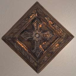
I’ve heard and seen the use of normal mapping many times, but I have never experimented with it myself, so I decided I should, just to learn something new. Normal mapping is a type of bump mapping. It is a way of simulating bumps on an object, usually in a 3D game. These bumps are simulated with the use of lights. To get a better sense of this technique, click on the image above to see a running demo. The example uses a 2D canvas and simulates Phong lighting.
So why use it and how does it work?
The great thing with normal mapping is that you can simulate vertex detail of a simplified object without providing the extra vertices. By only providing the normals and then lighting the object, it will seem like the object has more detail than it actually does. If we wanted to place the code we had in a 3D game, we would only need 4 vertices to define a quad (maybe it could be a wall), and along with the normal map, we could render some awesome Phong illumination.
So, how does it work? Think of what a bitmap is. It is just a 2D map of bits. Each pixel contains a color components making up a the entire graphic. A normal map is also a 2D map. What makes normal maps special is how their data is interpreted. Instead of each pixel holding a ‘color’ value, each pixel actually stores a vector that defines where the corresponding part in the color image is ‘facing’ also known as our normal vector.
These normals need to be somehow encoded into an image. This can be easily done since we have three floating point components (x,y,z) that need to be converted into three 8 or 16 bit color components (r,g,b). When I began playing with this stuff, I wanted to see what the data actually looked like. I first dumped out all the color values from the normal map and found the range of the data:
Red (X) ranges from 0 to 255
Green (Y) ranges from 0 to 255
Blue (Z) ranges from 127 to 255
Why is Z different? When I first looked at this, it seemed to me that each component needs to be subtracted by 127 so the values map to their corresponding negative number lines in a 3D coordinate system. However, Z will always point directly towards the viewer, never away. If you do a search for normal map images, you will see the images are blue in color. So it would make sense why the blue is pronounced. The normal is always pointing ‘out’ of the image. If it ranged from 0-255, subtracting 127 would result in a negative number which doesn’t make sense. So, after subtracting each by 127:
X -127 to 128
Y -127 to 128
Z 0 to 128
The way I picture this is I imagine that all the normals are contained in a translucent semi-sphere with the semi-sphere’s base lying on the XY-plane. But since the Z range is half of that of X and Y, it would appear more like a squashed semi-sphere. This tells us the vectors aren’t normalized. But that can be solved easily with normalize(). Once normalized, they can be used in our lighting calculations. So now that we have some theoretical idea of how this rendering technique works, let’s step through some code. I wrote a Processing sketch, but of course the technique can be used in other environments.
// Declare globals to avoid garbage collection

// colorImage is the original image the user wants to light
// targetImage will hold the result of blending the
// colorImage with the lighting.
PImage colorImage, targetImage;

// normalMap holds our 2D array of normal vectors.
// It will be the same dimensions as our colorImage
// since the lighting is per-pixel.
PVector normalMap[][];

// shine will be used in specular reflection calculations
// The higher the shine value, the shinier our object will be
float shine = 40.0f;
float specCol[] = {255, 128, 50};

// rayOfLight will represent a vector from the current
// pixel to the light source (cursor coords);
PVector rayOfLight = new PVector(0, 0, 0);
PVector view = new PVector(0, 0, 1);
PVector specRay = new PVector(0, 0, 0);
PVector reflection = new PVector(0, 0, 0);

// These will hold our calculated lighting values
// diffuse will be white, so we only need 1 value
// Specular is orange, so we need all three components
float finalDiffuse = 0;
float finalSpec[] = {0, 0, 0};

// nDotL = Normal dot Light. This is calculated once
// per pixel in the diffuse part of the algorithm, but we may
// want to reuse it if the user wants specular reflection
// Define it here to avoid calculating it twice per pixel
float nDotL;

void setup(){
  size(256, 256);

  // Create targetImage only once
  colorImage = loadImage("data/colorMap.jpg");
  targetImage = createImage(width, height, RGB);

  // Load the normals from the normalMap into a 2D array to
  // avoid slow color lookups and clarify code
  PImage normalImage =  loadImage("data/normalMap.jpg");
  normalMap = new PVector[width][height];

  // i indexes into the 1D array of pixels in the normal map
  int i;

  for(int x = 0; x < width; x++){
    for(int y = 0; y < height; y++){
      i = y * width + x;

      // Convert the RBG values to XYZ
      float r = red(normalImage.pixels[i]) - 127.0;
      float g = green(normalImage.pixels[i]) - 127.0;
      float b = blue(normalImage.pixels[i]) - 127.0;

      normalMap[x][y] = new PVector(r, g, b);

      // Normal needs to be normalized because Z
      // ranged from 127-255
      normalMap[x][y].normalize();
    }
  }
}

void draw(){
  // When the user is no longer holding down the mouse button,
  // the specular highlights aren't used. So reset the values
  // every frame here and set them only if necessary
  finalSpec[0] = 0;
  finalSpec[1] = 0;
  finalSpec[2] = 0;

  // Per frame we iterate over every pixel. We are performing
  // per-pixel lighting.
  for(int x = 0; x < width; x++){
    for(int y = 0; y < height; y++){

      // Simulate a point light which means we need to
      // calculate a ray of light for each pixel. This vector
      // will go from the light/cursor to the current pixel.
      // Don't use PVector.sub() because that's too slow.
      rayOfLight.x = x - mouseX;
      rayOfLight.y = y - mouseY;

      // We only have two dimensions with the mouse, so we
      // have to create third dimension ourselves.
      // Force the ray to point into 3D space down -Z.
      rayOfLight.z = -150;

      // Normalize the ray it can be used in a dot product
      // operation to get a sensible values(-1 to 1)
      // The normal will point towards the viewer
      // The ray will be pointing into the image
      rayOfLight.normalize();

      // We now have a normalized vector from the light
      // source to the pixel. We need to figure out the
      // angle between this ray of light and the normal
      // to calculate how much the pixel should be lit.

      // Say the normal is [0,1,0] and the light is [0,-1,0]
      // The normal is pointing up and the ray, directly down.
      // In this case, the pixel should be fully 100% lit
      // The angle would be PI

      // If the ray was [0,-1,0] it would
      // not contribute light at all, 0% lit
      // The angle would be 0 radians

      // We can easily calculate the angle by using the
      // dot product and rearranging the formula.
      // Omitting  magnitudes since they are = 1
      // ray . normal = cos(angle)
      // angle = acos(ray . normal)

      // Taking the acos of the dot product returns
      // a value between 0 and PI, so we normalize
      // that and scale to 255 for the color amount
      nDotL = rayOfLight.dot(normalMap[x][y]);
      finalDiffuse = acos(nDotL)/PI * 255.0;

      // Avoid more processing by only calculating
      // specular lighting if the users wants to do it.
      // It is fairly processor intensive.
      if(mousePressed){
        // The next 5 lines calculates the reflection vector
        // using Phong specular illumination. I've written
        // a detailed blog about how this works:
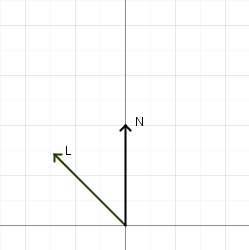
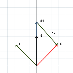
        // https://andorsaga.wordpress.com/2012/09/23/understanding-vector-reflection-visually/
        // Also, when we have to perform vector subtraction
        // as part of calculating the reflection vector,
        // do it manually since calling sub() is slow.
        reflection = new PVector(normalMap[x][y].x,
                                 normalMap[x][y].y,
                                 normalMap[x][y].z);
        reflection.mult(2.0 * nDotL);
        reflection.x -= rayOfLight.x;
        reflection.y -= rayOfLight.y;
        reflection.z -= rayOfLight.z;

        // The view vector points down (0, 0, 1) that is,
        // directly towards the viewer. The dot product
        // of two normalized vector returns a value from
        // (-1 to 1). However, none of the normal vectors
        // point away from the user, so we don't have to
        // deal with making sure the result of the dot product
        // is negative and thus a negative specular intensity.

        // Raise the result of that dot product value to the
        // power of shine. The higher shine is, the shinier
        // the surface will appear.
        float specIntensity = pow(reflection.dot(view),shine);

        finalSpec[0] = specIntensity * specCol[0];
        finalSpec[1] = specIntensity * specCol[1];
        finalSpec[2] = specIntensity * specCol[2];
      }

      // Now that the specular and diffuse lighting are
      // calculated, they need to be blended together
      // with the original image and placed in the
      // target image. Since blend() is too slow,
      // perform our own blending operation for diffuse.
      targetImage.set(x,y,
        color(finalSpec[0] + (finalDiffuse *
                            red(colorImage.get(x,y)))/255.0,

              finalSpec[1] + (finalDiffuse *
                          green(colorImage.get(x,y)))/255.0,

              finalSpec[2] + (finalDiffuse *
                         blue(colorImage.get(x,y)))/255.0));
    }
  }

  // Draw the final image to the canvas.
  image(targetImage, 0,0);
}
Whew! Hope that was a fun read, Let me know what you think!


